this is a shot showing one of the SCAT h beam connecting rods i'm using.these are high quality pieces and there price makes them even more attractive when building a performance motor.once again i have tried to do my best to take more accurate photos,but its not always possible.lets check the rods and bearings.
the lenght is 5.394 \" which is determined by measuring from the centre points of the wrist pin bore and the rod bearing bore,the bore guage is used to measure the radial oil clearance of the connecting rod bearing after it is fully torqued up and the telescoping bore guage is used to measure the wrist pin bore.

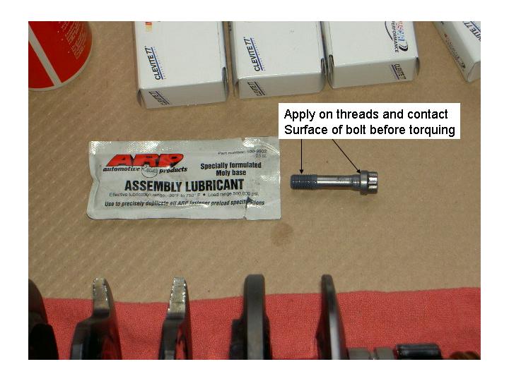
the rod bearings i'm using are CLEVITE 77 ROD BEARINGS these are a high quality bearing that are made to take the shock loads in high performance/race engines.these bearings are standard vw rod journal size and were purchased locally at HIGH PERFORMANCE ENGINES IN BURNABY.next time i will also use there main bearing set which i believe can be orderd with extra .001 \" oil clearance!!
you need to apply special supplied grease on 2 spots of the rod bolts,the reason is to reduce friction when torqing the rods ,that way a more acurate reading is given.
you have probably heard of so much discusion on rod bolt stretch ,since i don't have a actual arp rod bolt stretch gauge ,and for that matter have never used one i will show you another way to check your bolts.first you need to know that once something is tight any time you go past that point you are applying torque to the fastner ,which in the end causes it to stretch.don't stretch it enough and it could loosen or if you over stretch it it may snap.if i remember for these bolts when torqued they should have around .005-.006 inches of stretch.in fact i tested all mine and found one that stretched .008 so i have replaced the set.
rod bolts are very important .they are the only link keeping your connecting rods together during high rpm .you can imagine at times that the upper portion of the rod will try to seperate from the lower section do to inertial and load.that is why these bolts are extremely strong and have such huge tensile strength,around 190,000-200,000 psi.so acurate measurements are needed for reliable operation.
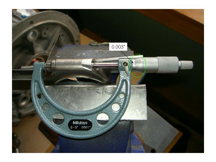
each rod was assembled with a main bearing set installed .with the bolts lubed upboth bolts were snugged hand tight and measured.a point was taken on the micrometer scale and noted.in this case it ended up lineing up at .003\"
with the rod now supported in a pair of soft jaws in my vise its ready to torque up.this is very important as it will protect the rod and allow a secure way to hold when torquing.

torqued to 42 ft/lbs
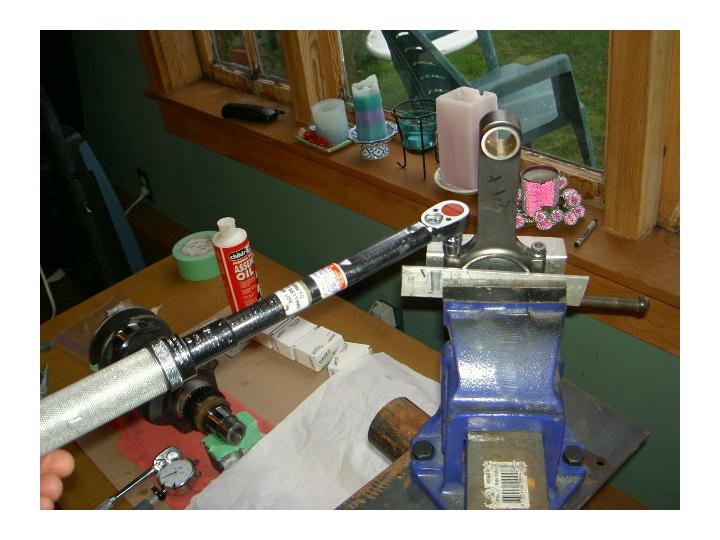
once the rod is torqued again it was mounted sideways in the vise and the bolts remeasured .in this case i have now .008\" .so .008\"-.003\"=.005\" stretch at 42 ft/lbs=ok!!

now i now this isn't the best way but hey if you use your head there are always more ways to do things,the reason there is a thick feeler guage on one end is just to give a level platform for the micrometer to sit against.notice the spot where i had clearanced the rods to clear my case.
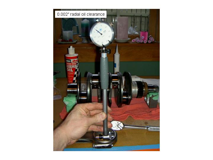
since its all torqued i set my bore guage to my measurement from my spec sheet of the cranks rod journal diameter of 2.1647\"and measured the radial oil clearance of my rod bearings .good at just over .002\",again next time i would have this measurement first and have my crank ground to allow .003\" radial clearance
when ALL THE RODS BOLTS ARE CHECKED AND ALL THE RADIAL CLEARANCES CHEKED ON ALL 4 all parts were disassembled.
there is a few more steps to go before those rods get bolted onto the crank,here we go.remember all parts will stay in the exact spot and will should never get mixed up during this process.
rod caps measured at 0.8925\"

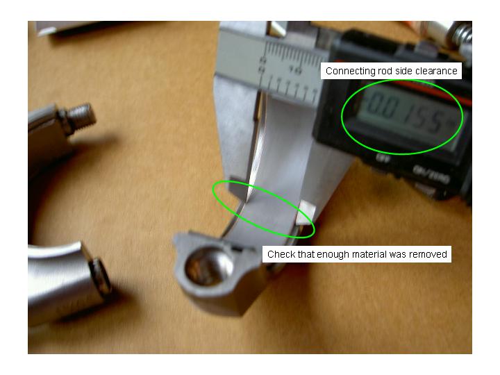
after the measurement of the rod cap is taken i zero the caliper and transfer it between the cranks rod journal width,when the caliper is expanded it will give you a rough measurement for rod side play .in this case 0.016\"

measure rod bearings 0.6890\"

caliper measurment of rod bearing width is compared to ground surface on crank.note its pretty much the same so the bearings will need to be modified and rechecked.

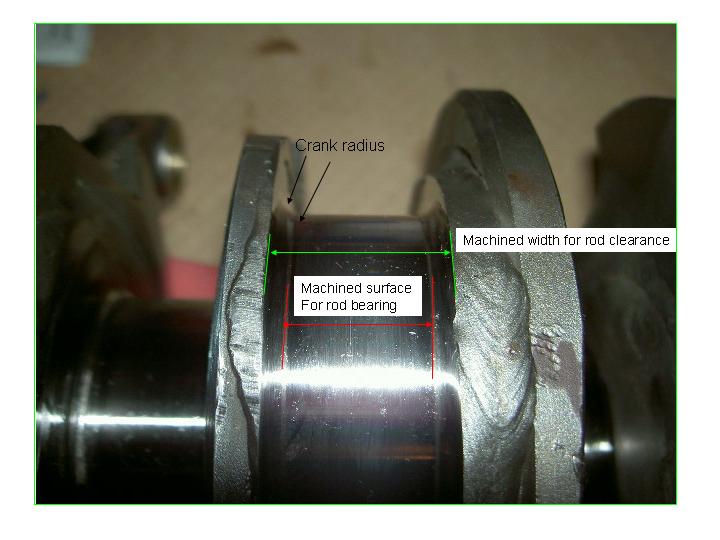
you can see in this photo a better shot of the ground bearing surface width as well as the radius from the ground surface to the cranks webs.it is this radius that gives the crank its strenght against bending but is also causes a point for bearing contact.
one more time,a better photo showing radius/machined surface for bearing and machine width for rod side clearance.
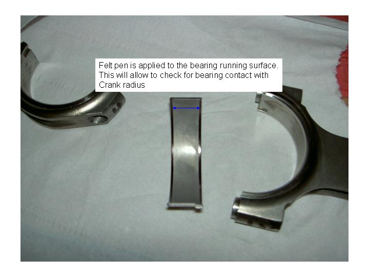
since i know i have radial clearance and rod side clearance its time to closer check the bearings for contact with the crank radius.i apply felt pen to the top of each bearing sides,when the felt drys a lite film of oil is applyed to the bearins and the rod is assembled on the crank and torqued up to specs.
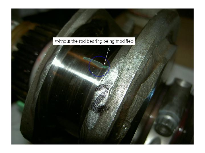
with the rod pushed against one side of the crank then the other side and rotated a bit back and fourth .once disasembled it can be inspected for contact.in this case you can see that the outer edge of the bearings do infact touch the crank radius.

a differant way to check is also to apply a small piece of plastiguage on the crank covering into the radius and with the large part of the conecting rod with one bearing shell installed in it place it into the d=crank fullagainst one side and push down squarly into the crank.notice the bearing edge contact point is at the very edge of the groung bearing surface.again just another way to double check for rod bearing contact.
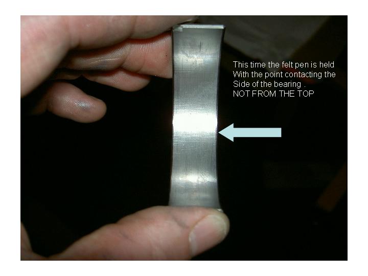
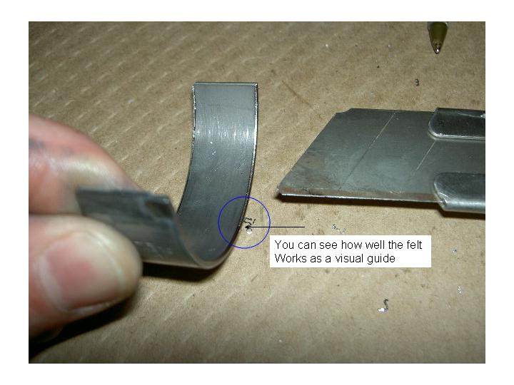
now this time felt pen is aplyed to the sides of the bearings ,this will act as a visual guide.
this is how i modifie my bearings using a olfa knife.you can see i hold it at about a 45 deg angle and push the knife away from me.you need to practice on a old bearing to get this technic down first.

now you can see why the felt is needed it really helps keep things true.
both edges done.

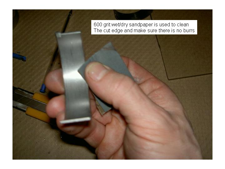
holding the 600 grit emery paper at a 45 deg angle the cut edges are lightly sanded to make sure there is no sharp edges,then using brake clean the bearing is fully cleaned.
with the cleaned bearing back in the conecting rod cap the caliper is set to the bearing widt of 0.8925\" minus .015\" for side clearance and the bearing is checked to make sure it is narrowed enough on both sides.
now using the same plastiguage meathod as befor you can see the added clearance.now only 7 more bearing shells to go

now before the rods bolt up i always do one last trial fit and double make sure the bearing ends alighn,remember they can be moved to line up and its very important to check,also note the bearing tangs should locate down towards the cam.this is done for the reason of allowing more oil spill off to go directly back onto the cam and to the oil pan instaed of onto the case roof.

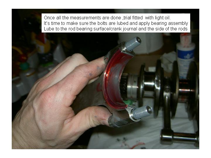
ahh my fingers!!!!nope just kiding,since everthing is good now and everthing is tripple checked a good dose of assembley lube is used on the bearing surfaces and the rod sides.now this rod is going to used for checking TDC/DECK HEIGHT /AND CASE CENTRELINE.all other rods were installed and checked for side clearnce and rapped up waiting for finall assembley.
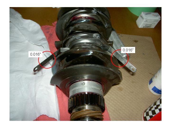
as noted all rods had there side clearance checked this is done by having the rod fully torqued up on the crank and pushed to one side.i like to use 2 feeler guages in order to make sure it is contacting evenly.
this case this rode has 0.016\" side clearance.
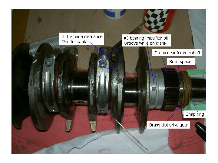
i set this phot up so you can actualy see the rod side clearance as well as the way the #3 bearing sits[modified later for oil groove on the crank,very difficult]
the order in which it goes is #bearing/cam gear/solid spacer/brass dist gear/snap ring.
will try to get a picture of the #3bearing and end gear assembley from another motor when i get a chance as well as all lubes used.
good night