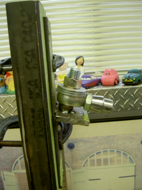
the inner pivot point has been lowered 1 1/2" but the 3/4" bolt retains the stock pivot point angle .the heim joint sits on the bolt and the 3 washers are stacked on top .the first washer has the ID bored to allow the inner ball of the heim joint to sit inside it and the other 2 washers when tightened down square the complete assembly and stop all movement .
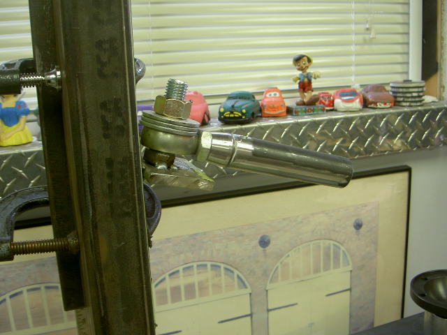
added the 4" piece of tubing up onto the threaded tube collar ,break out the tig and tack the tube to the collar .the threaded collar allows the heim joint to adjust in and out as well as gives a good solid welded connection
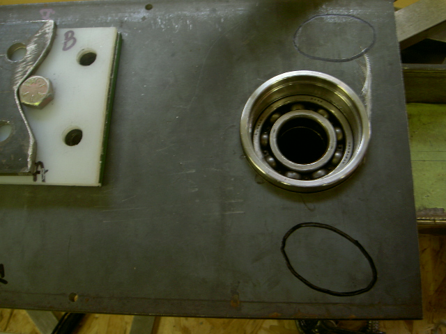
now a picture i do not have is of the master bearing plate template , when i pinned the two 3/8" bearing plates together to bore the 2 7/8" hole i also decided to pin 1 more piece of 1/4" plate to them .now i had a master plate to work from .and as i worked on the first control arm , any hole that was drilled was also copied to the 1/4" master so it was just a matter of pinning the 1/4" master to the new 3/8 " bearing plate and use it as a guide for boring the needed fwd 1/2" mounting holes , worked fantastic.also i kept a thin cardboard template that i laid over the 3/8 plate and marked the location of the diagonal tubes .it will make sense as the pictures come up .
with the new bearing plate fwd holes drilled and diagonal arm holes marked time to mount up the new bearing plate to the jig.
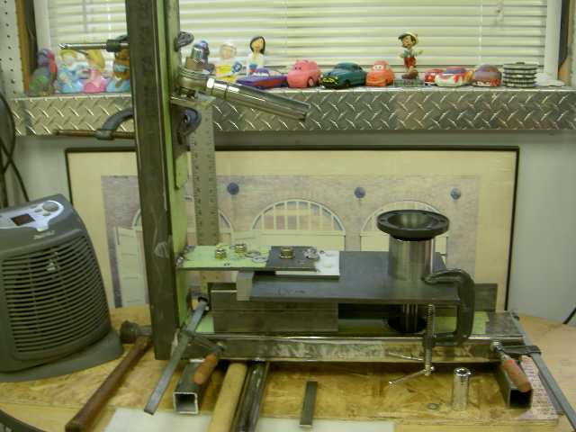
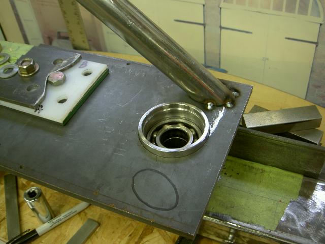
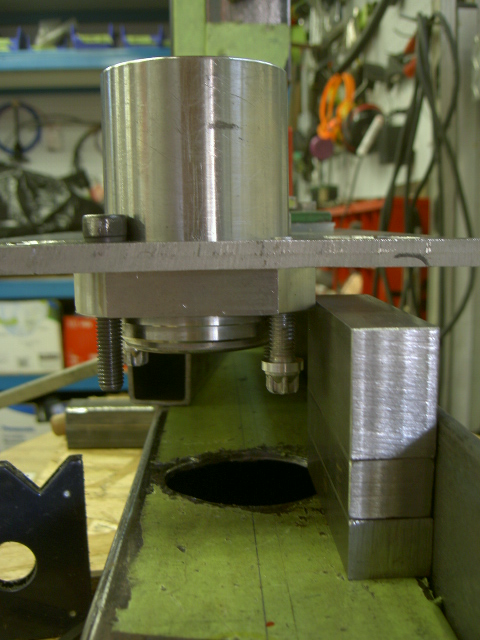
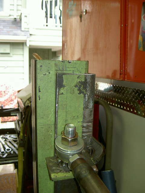
i had mentioned before how the jig is made universal, and it does not matter whether you are making a left or right arm they will turn out the same .this is how the bearing plate and bearing housing mount and get squared/centered to the jig or in this case raised 3/4" up .
on the right side of the jig is a fairly heavy piece of angle iron clamped to the lower side of the jig used as a guide , and for reference if a 1/4" shim was laid vertically against it. then the outer edge of the bearing housing was slid over to touch it the stub axle would be 100% dead centre to the complete assembly , look at the pen mark on the green tape it shows the centre of the lower part of the jig. what has happened now is there are 3 blocks all 1" thick .i needed to stack them to get the height .so take out the 1/4" shim and add back 1" of shims between the bearing housing and the heavy angle iron guide and when the bearing housing is slid over and just touches the 1" shims, the assembly has just been raised 3/4" above the centre line .at this point the 1 fwd bolt was tightened very well to keep it all in place .
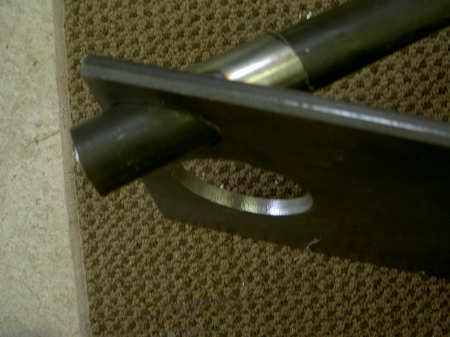
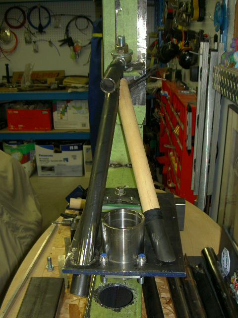
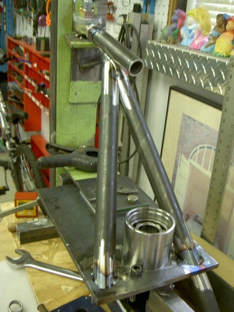
time to get the diagonal arms in , sorry i do not have a picture of the tube notching jig in use , i will see if i have one and post it .but like i said i made duplicates of all pieces when the first arm was made .now something i did was use 1 1/4" wooden dowels to test all my angles .way easier to keep trimming wooden dowels than steel tube .once i was happy with the fit and angle i would just replace the wooden dowel in the jig with the 1 1/4" dom tubing and cut the same notch . in this photo i have taped the first diagonal test dowel to the 4 " stub piece from the heim joint and with a thin wall 1 1/4" ID tube slide over top of it with the end cut at the correct angle .
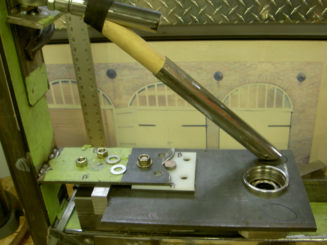
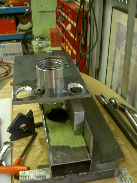
slide the tube down the dowel and line it up onto the marked holes.you can see something is odd here .there are white shims between the 3/8" bearing plate and the mounting arm welded to the vertical arm of the jig.the mounting arm is welded to the vertical arm of the jig at 90 deg and its centre mounting hole is again centered to the jig .if you remember in the earlier photo with the stock test arm it does represent the length of a stock spring plate .that's all can say for now.
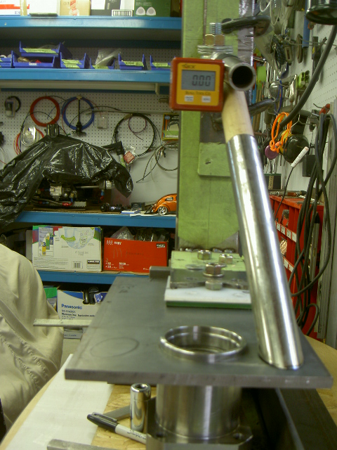
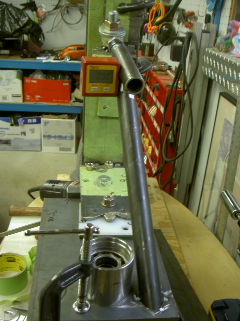
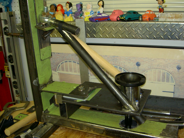
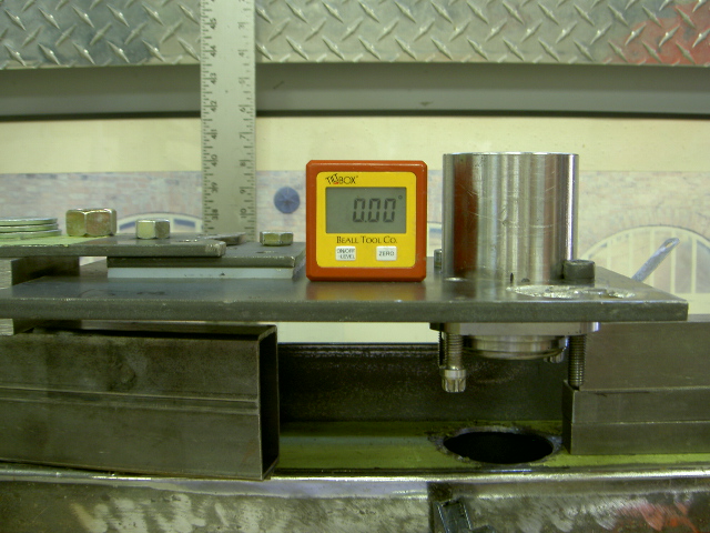
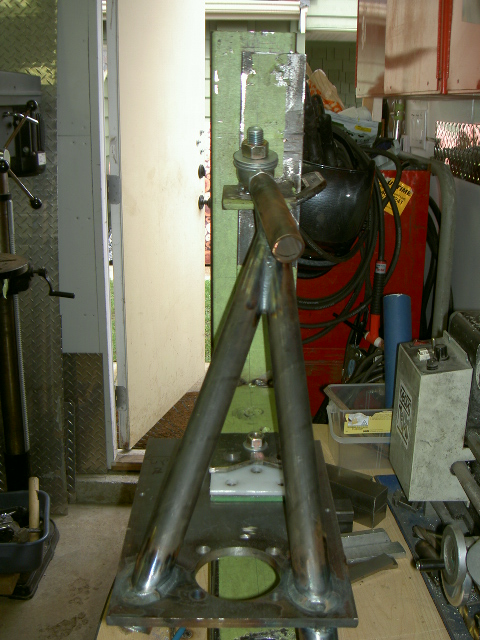
if you dont own one go buy one of these level boxes , they are magnetic and are fantastic to work with .i think i paid under $ 25 up the road at lee valley for it .the complete jig is level in both directions and keeping things equal and square are a must when trying to duplicate left and right parts .here the 4" stub tube and the first diagnal tube are squared up .you can see the inner pivot and mounting plate centre hole lining up centered as well
tack the lower thin wall tube to the bearing plate
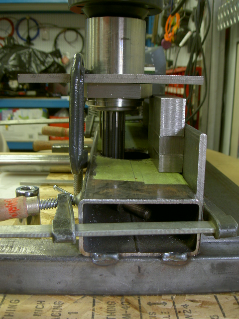
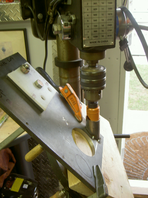
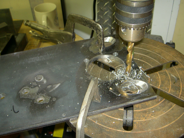
the lower bearing plate is again removed from the jig and the thin wall tube is cut leaving about 1 1/2" on the short side .simple now loosen the drill press bed .and wind it up against the 1 1/4" hole saw .it almost adjusts itself , well almost .snug up the height and bed angle pinch bolts and clamp the assembly to the drill press .test the setup by raising and lowering the hole saw into the tube , it should go with no binding .
drill away as the thin wall tubing is now the perfect hole saw guide .
test fitting a piece of the 1 1/4" dom tubing and it passes through no problem . it was decided to do this instead of welding to one side of the 3/8' bearing plate as welding from both sides as well as the tube passing through the plate would be allot stronger .
back to the jig and mount it all up again , square up the lower bearing plate as before , slide the new first diagonal arm into place and using the level box square it up .
sorry had to use a photo from the first arm , but i think you get it , same thing again using the wooden dowel for test fit and the thin wall tubing as a welded in guide .
remove again and mount back to the drill press as before and bore the 2nd 1 1/4" hole through the plate
something i have not mentioned is how difficult it was to design the arm and actually get room for the shock and 930 flange to clear and work together . i lot of sleep was lost over it but it all worked out .this shows the holes in the bearing plate drilled and the bearing housing bolted to the plate with the stub axle in place .just making sure it clears as it is tight.
the complete assemble was again removed, the 4 bolt holes for the bearing housing were marked and drilled . you can now see the fwd 4 bolt holes , i will tell you the most fwd stock location one will go.
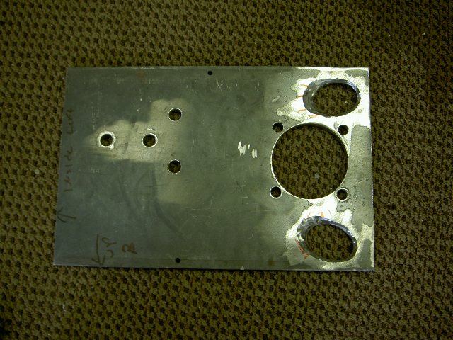
here it is the completed lower plate , wow that's a bit of drilling .its in the process of getting all the scale cleaned and prepped for welding .where the red marks are points i would bevel out more to allow for better welding penetration .
quick view, time to get it done . bearing housing bolted to bearing housing plate and shim blocks back in place
slide assembly over just till it touches the 1" shims and snug up that 1 centre bolt ,note the notched diagonal tubes prepped and ready to go
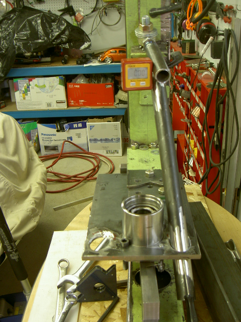
make sure its level
slip in the lower diagonal tube and 4" stub tube and square it up .tack it in place
install top diagonal tube and tack it in place
tig welded and left in the jig to cool
this is something i did not notice right away .the top pivot point was actually pulled down 3/16"
no problem its still all square and gives a bit more clearance to play with on the torsion tube
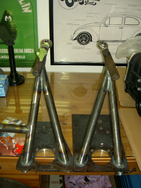
all done both arms .the finnished arm just needs to be trimmed and smoothed